Learn - Feb. 01, 2023
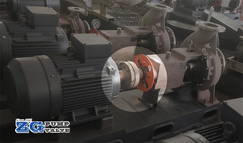
During the process of installation centrifugal pumps on-site, or in the routine maintenance of centrifugal pumps, it is necessary to align the couplings to ensure the smooth operation of the pump equipment. We are professional and have rich experience for the installation and maintenance of centrifugal pumps.
In five minutes, you will know the way of fast and accurate alignment of centrifugal pump couplings.
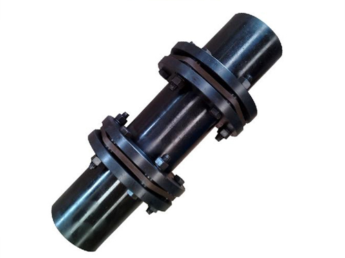
A centrifugal pump coupling is used to connect the motor shaft and the pump shaft, its role is: 1. Transfer torque; 2. Compensate the relative displacement and deviation of the two shafts on the axis; 3. Vibration reduction and buffering. Most of centrifugal pump units are connected by diaphragm couplings. Diaphragm couplings are connected by a flexible diaphragm between the half coupling and the intermediate connecting sleeve.
The alignment of the centrifugal pump coupling means that the center lines of the two axes of the motor shaft and the pump shaft coincide with each other.
The result of alignment centrifugal pump couplings will directly affect the service life of the flexible diaphragm of couplings. The more precise the alignment of the couplings, the better. If the deviation is too large, it will cause large vibration, accelerate the wear of parts, and even lead to the damage of the pump.
If in accordance with the theoretical requirements, to achieve the centrifugal pump couplings accurate alignment, the need for precision alignment instruments. But the working conditions on-site are often rudimentary, sometimes there are even no engineers, and workers rely on experience to do the alignment job.
It is necessary to introduce some methods of rapid and accurate alignment of centrifugal pump couplings by using traditional measuring tools, which can shorten the time of couplings’ alignment and improve the efficiency of construction and maintenance.
First, we analyze several cases where the couplings are out of alignment
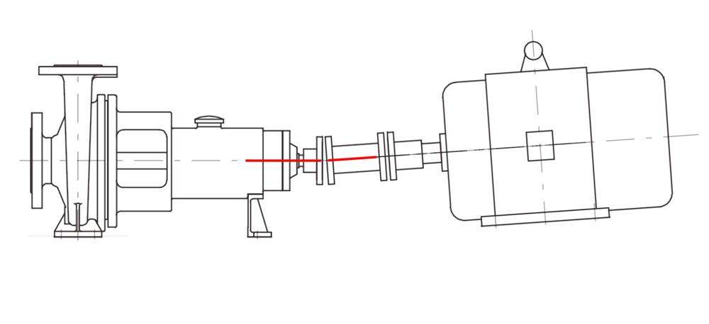
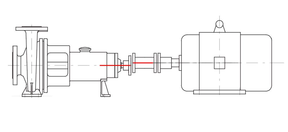
1. The center line of the shaft of the motor and the shaft of the pump does not coincide, but is parallel to each other, and there is radial displacement; 2. The center line of the two axes intersects at the center of the semi-coupling, and there is angular displacement; 3. Both axes have radial displacement and angular displacement.
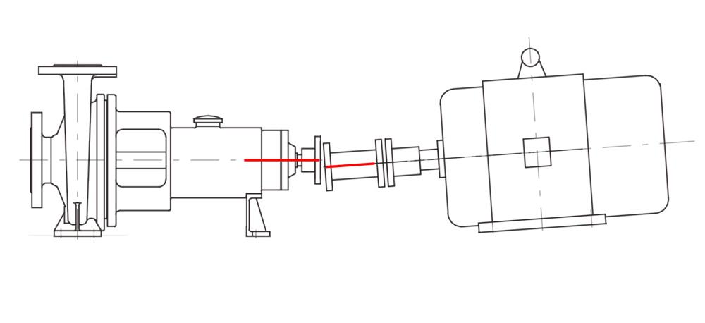
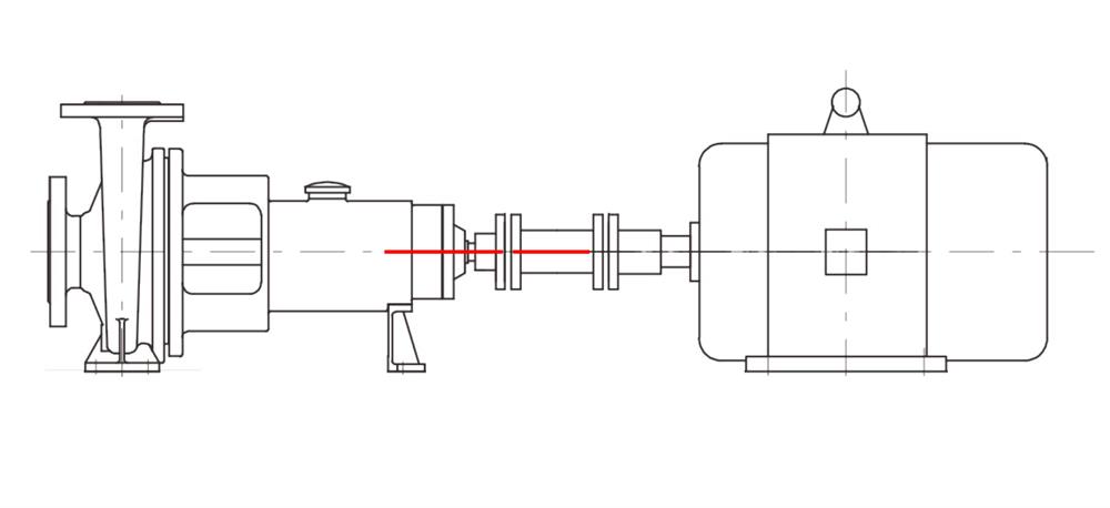
2. Quick and accurate alignment of coupling
At the installation or maintenance site, the pump is fixed, and the motor is moved to align by adjusting the adjusting bolt of the motor base and increasing or decreasing the copper gasket. Coupling alignment is usually carried out by two table alignment method. Two table alignment method is the most common method of alignment of centrifugal pump coupling. First, the table frame is fixed on the half coupling A, and then two dial gauges are installed in the axial and radial positions of the table frame, one of which is used to measure the transfer value of the end face of the half coupling B, and the other is used to measure the radial runout value of the half coupling B.
Take a point on the end face of the coupling as the starting point, read the radial and axial values of the two dial gauges respectively, denoted as a1, b1; Then turn the two half couplings together to 90°, 180° and 270° from the starting point and record the dial indicator values a2, b2, a3, b3, a4, b4 in the radial and axial directions. The measured data are analyzed and calculated, and coupling alignment is carried out by adjusting motor adjusting bolts and increasing or decreasing gaskets.
Alignment algorithm
The four feet on the motor are numbered. The two feet near the coupling end are denoted as foot 1 and the other two as foot 2. The axial distance between supporting foot 1 and the coupling dial meter measuring point is L1, and the axial distance between supporting foot 2 and the coupling dial meter measuring point is L2. The diameter of the circle formed by the dial meter measuring point on the coupling is D when it is rotated around the shaft center.
The adjustment amount of foot 1 in the vertical direction is:
δ1=L1/D *(b3- b1)+(a3-a1)/2
The adjustment amount of foot 2 in the vertical direction is:
δ1=L2/D *(b3- b1)+(a3-a1)/2
The adjustment amount of foot 1 in the horizontal direction is:
δ2=L1/D *(b4- b2)+(a4-a2)/2
The adjustment amount of foot 2 in the horizontal direction is:
δ2=L2/D *(b4- b2)+(a4-a2)/2
Improved alignment algorithm
After the adjustment of the horizontal direction and vertical direction of each foot is obtained, the motor can be adjusted according to the calculation results. In the vertical direction, as long as the corresponding thickness of the gasket can be increased or reduced according to the calculation results, while in the horizontal side by adjusting the bolt to control the motor adjustment amount.
A feasible method is to indicate the horizontal adjustment of each foot of the motor through the radial dial indicator in the horizontal direction.
When the adjustment is made by adjusting the adjusting bolt of foot 2, the movement of the dial indicator pointing to 0 is:
△1=L2·tan- 1 [ δ1/ (L2-L1) ] / cos { tan- 1[ (b3- b1)/ D ] }
When the adjustment is made by adjusting the adjusting bolt of foot 1, the movement of the dial indicator back to 0 is:
△2=L1·tan- 1 [ δ1/ (L2-L1) ] / cos { tan- 1[ (b3- b1)/ D ] }
It should be noted that after adjusting the horizontal direction of a support foot, it is necessary to re-measure the runout value of each point of the dial indicator on the coupling and recalculate △1 and △2. The algorithm of alignment of centrifugal pump coupling, integrated with computer software, can quickly obtain reliable reference number on the site of centrifugal pump installation and maintenance.
