Learn - Dec. 12, 2022
According to the installation of different types, mixed flow pumps can be divided into horizontal mixed flow pumps, vertical mixed flow pumps.
A Horizontal Mixed Flow Pump is a kind of pump between single stage end suction centrifugal pump and horizontal axial flow pump. It has the characteristics of large flow rate, medium head, high efficiency and wide application range. Horizontal mixed flow pumps have the advantages of short axial size, stable operation, simple structure and convenient installation.
A vertical mixed flow pump is a vertical, single-stage guide vane type mixed-flow pump, with high efficiency, large flow, good cavitation performance, small footprint, no need to vacuum before use.
According to the form of the pressure chamber, mixed flow pumps can be divided into guide vane mixed flow pumps, volute mixed flow pumps.
Guide vane mixed flow pumps and horizontal axial flow pumps are very similar, the role of the guide vane is to collect the liquid thrown out of the impeller, reduce the kinetic energy of the liquid, convert some kinetic energy into pressure energy, and then uniformly lead into elbow tube to discharge. Guide vane type mixed flow pump radial size is small, they are suitable for the head between 10-20 meters.
Volute mixed flow pumps and volute centrifugal pumps’ structure are more similar, the volute type mixed flow pump through the volute collection of liquid, complete energy conversion. The structure of a volute mixed flow pump is simple, also has some advantages: its pump body along the radial diffusion, so the axial size is short, the unit runs stably. Volute mixed flow pumps are suitable for low head, large flow working conditions.
Usually, the specific speed is required to exceed 400, and it is generally designed as a guide vane mixed flow pump, also known as the diagonal flow pump.
Zigong Pump & Valve has conducted in-depth research on the hydraulic performance of mixed flow pumps. Our company and Xihua University jointly set up the fluid laboratory, which makes extensive use of Computer Fluid Dynamics (referred to as CFD). CFD numerical simulation is used to study the fluid motion inside the pump body and test the efficiency and performance of the pump. It provides data support and theoretical basis for hydraulic optimization, impeller optimization and guide vane optimization of mixed flow pumps. The constant exploration of fluid machinery makes the mixed flow pumps produced by our company, with high efficiency, stable operation, far superior to the quality of similar products.
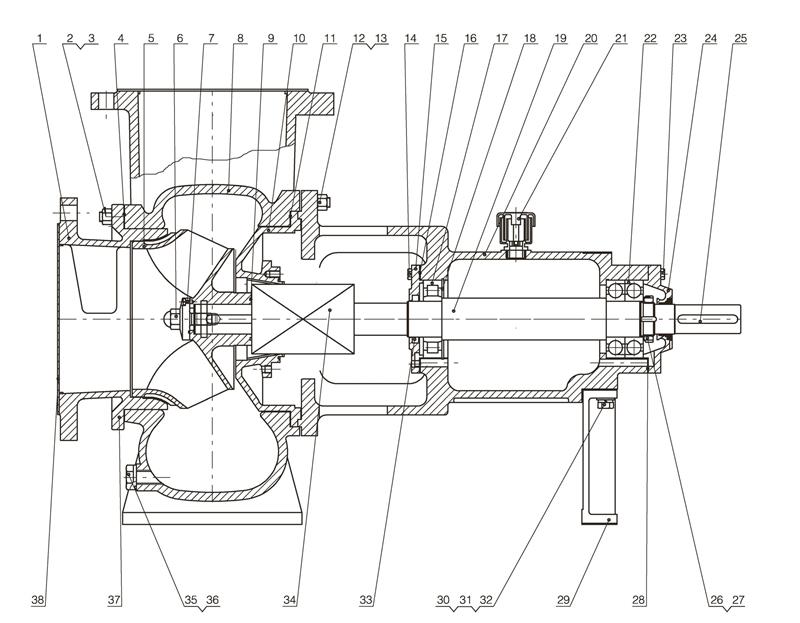
| 1.Water-absorbing room | 14.Bolt | 27.Tab washer |
| 2.Stud | 15.Front bearing cover | 28.Back cover pad |
| 3.Nut | 16.Front cover pad | 29.Bracket |
| 4.Gasket | 17.Bearing | 30.Bolt |
| 5.Impeller | 18.Circle lips for holds | 31.Flat washer |
| 6.Impeller nut | 19.Shaft | 32.Spring washer |
| 7.Anti-rotation screw | 20.Frame | 33.Skeleton oil seal |
| 8.Pump casing | 21.Air vent cover | 34.Mechanical seal |
| 9.O-ring | 22.Bearing | 35.Pipe plug |
| 10.Pump casing | 23.Bolt | 36.O-ring |
| 11.Gasket | 24.Back bearing cover | 37.O-ring |
| 12.Stud | 25.Key | 38. |
| 13.Nut | 26.Small round nut | Seal |
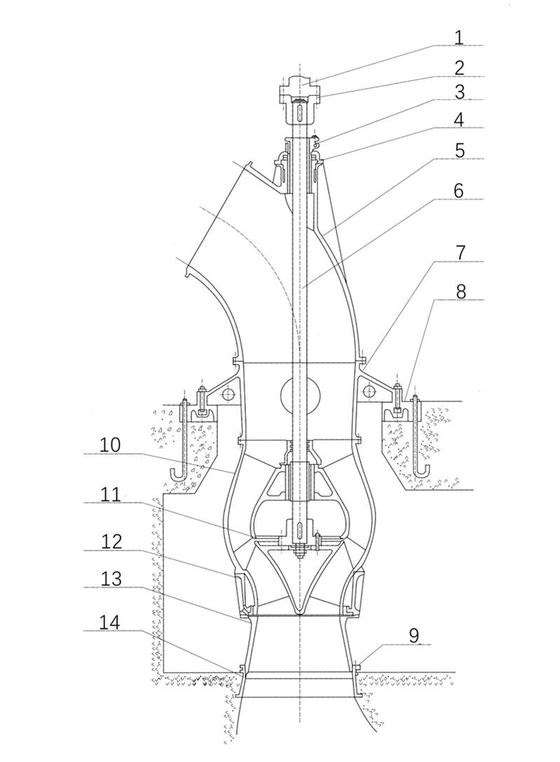
| 1.Driving shaft | 6.Shaft | 11.Impeller |
| 2.Coupling | 7.Pump base | 12.Impeller casing |
| 3.Stuffing | 8.Soleplate | 13.Inlet pipe |
| 4.Rubber bearing | 9.Stuffing ring | 14.Base plate |
| 5.Elbow | 10. Guide vane body |
Mixed Flow Pumps are between single stage end suction centrifugal pump and horizontal axial flow pump in performance and structure. It has the advantages of centrifugal pump and axial flow pump: the use of flow, head variation range, wide efficient zone, reasonable design can avoid the saddle zone performance curve phenomenon, stable operation and so on.
Next, we introduce the application of mixed flow pump in the water industry, and show the case of our mixed flow pumps.
1. Sewage treatment plant
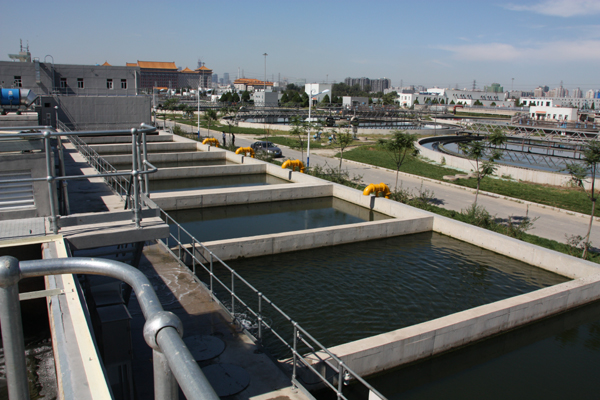
The sewage treatment plant is located in a big city with a population of 10 million. The design scale is 1 million m 3 /d in the near future and 2.5 million m 3 /d in the long term. The main processing structures are inlet pump room; Aerated sand sedimentation tank; Primary sedimentation tank; Aeration tank; Blower room; Secondary sedimentation tank; Reflux sludge pump house; Surplus sludge pump house; Sludge enrichment tank; Sludge digester; Sludge dewatering room; Wet gas storage tank; Desulfurization plant; Biogas generator room, etc. The design scale of the inlet pump room is 1 million m 3 /d, and 6 vertical sewage mixed flow pumps are set, with 4 installed in the first phase and 2 installed in the second phase. The pump performance is as follows: Q=3m 3 /s, H=15m, n=492r/min, η=80%, pump output power is 600kW.
2. Coal-fired thermal power plants
Coal-fired thermal power plant is mainly composed of heat engine, boiler and boiler water supply equipment. The modern thermal power plants use steam turbines as heat engine. The combination of a condensing system and a feedwater heating system requires at least three kinds of pumps: 1. Condensate Pump: transfer the condensate out of the condenser hot water tank; 2. Boiler feed water pump; 3. Circulating pump: Cooling water flows through the condensing pipe to condense the steam discharged from the steam turbine.
A circulating water pump is one of the important large auxiliary machines of thermal power equipment. Its main function is to transport cooling water to the condenser, that is, to transport the normal temperature water equivalent to 50 ~ 70 times of the boiler steam volume by circulating pump, so that the steam through the turbine condenses into condensed water.
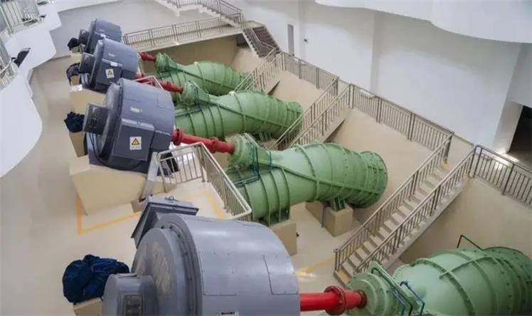
A thermal power station: The model 600 HLB vertical oblique flow pump is configured for 300MW thermal power unit, with a single pump power of 1600kW; B thermal power station: The model 1800 HLB vertical oblique flow pump is configured for 600MW thermal power unit, with a single pump power of 2500kW. They are the larger energy-consuming equipment in thermal power units.
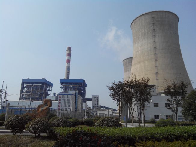
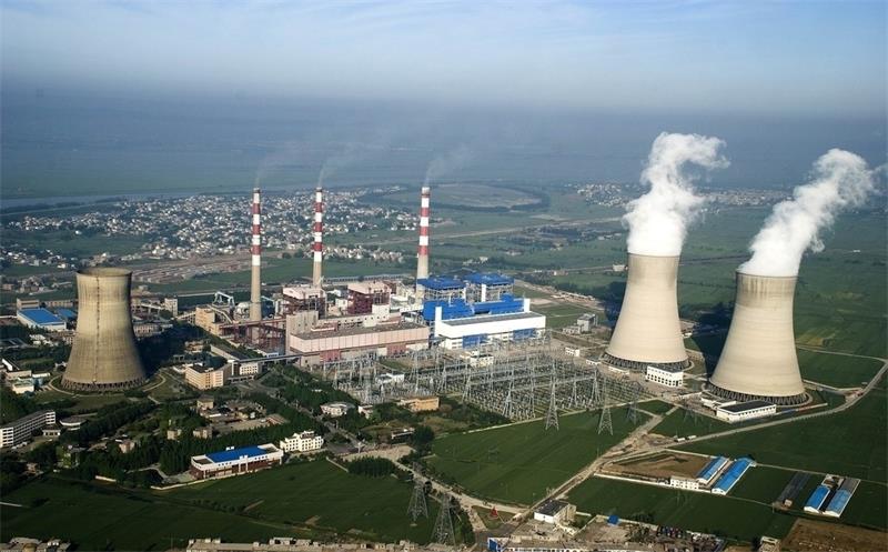
The performance parameters of these two pumps are shown in Table 4.
| Pump model | 600HLB | 1800HLB |
| Flow rate ( m3/h ) | 1600 | 31680 |
| Head ( h ) | 25 | 20 |
| Speed ( r/min) | 495 | 370 |
| Power ( kW ) | 1600 | 2500 |
| Discharge dia. ( mm ) | 1400 | 1800 |