Learn - Feb. 05, 2025
We often talk about the multistage pump, suitable for long-distance pumping water, or physical and chemical properties similar to clear water. But what if you need to pump a slurry, a medium containing particles, at high pressure and high head? Of course, there are solutions, pump manufacturers for customers to solve a variety of fluid delivery problems.
The Self-balancing wear-resistant multistage pump is a type of multistage pump used for transporting medium containing solid particles or slurry, meeting the requirements of high pressure and high head. Now you have a better understanding of what a self-balancing wear-resistant multistage pump is. This robust pump is specifically designed to handle challenging applications, ensuring reliable operation in the transportation of high-pressure, high-head slurries containing particles.
- Chapter One Brief Introduce Self Balancing Wear Resistant Multistage Pumps
- Chapter Two Hydraulic Design Of Self Balancing Wear Resistant Multistage Pump
- Chapter Three Structure Design Of Self Balancing Wear Resistant Multistage Pump
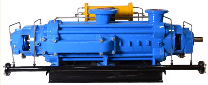
We will describe the self-balancing wear-resistant multistage pump in three chapters. 1. Brief introduce a self balancing wear resistant multistage pump, and compared with D series multistage pump in structure; 2. Optimize the hydraulic model of the flow parts of self balancing wear resistant multistage pumps; 3 The structure of the heavy duty wear resistant multistage pump is optimized. We manufacture high-performance wear-resistant multistage pumps. We optimize the hydraulic design, select wear-resistant materials, and enhance the efficiency and service life of the pumps.
Self balancing wear resistant multistage pumps handle medium containing solid particles, compared with D series multistage pumps, there are many different points in the structure.
Slurry long-distance delivery, the slurry refers to: specific gravity is greater than water (1.1-1.5t/m3), there is a certain solid content (concentration of 10%-60%) of the fluid. Flow range in dozens to hundreds of cubic meters per hour, the head is generally more than 200 meters, sometimes up to thousands of meters. The D type multistage pump can not transport medium containing particles.
The structure of D type multistage pump adopts the segment-type multistage pump with the impeller arranged in the same direction (Figure 1-1), and balances the axial force by the balance discs or the balance drum. This structure form is easy to be worn, thus affecting the service life of the pump, and the leakage is large, affecting the pump operation efficiency.
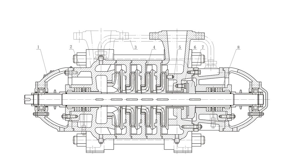
1-1 Structural diagram of D-type multistage pump
| 1. Driving end bearing unit | 2. Suction casing | 3. Equalizing pipe |
| 4. Guide vane | 5. Balance sleeve | 6. Balance ring |
| 7. Balance disc | 8. Mechanical seal |
Self-balancing multistage pump has carried out innovation on the structure of D type multistage pump, self-balancing multistage pump cancellations the balancing device, (that is, there is no balance disc friction loss and no balance reflux loss), so the self-balancing multistage pump efficiency is 5-14% higher than the same category of multistage pump. At the same time, it solves various faults such as wear of the balance disc and balance disc seat or rotor seizure caused by the failure of the balancing device, greatly extending the service life of the pump.
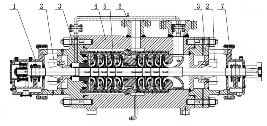
Structural diagram of self-balancing wear-resistant multistage pump
| 1. Driving end bearing component | 2. Mechanical seal | 3. Pump casing |
| 4. Pump body | 5. Impeller chamber | 6. Equalizing pipe |
| 7. Non-driving end bearing component |
Self balancing wear resistant multistage pumps are widely used in coal chemical industry as a scrubber feed pump, metallurgy industry for system high pressure water transport, coal mine for coal mine pit water transport, thermal power plant for boiler feed water and mine tailings transport, etc.
Nowadays, heavy duty wear resistant multistage pumps have made a lot of breakthroughs in structure, hydraulics and materials. They are suitable for long-distance transportation of medium containing particles or heavy gravity solution. The pump set has the advantages of reliable operation and long service life.
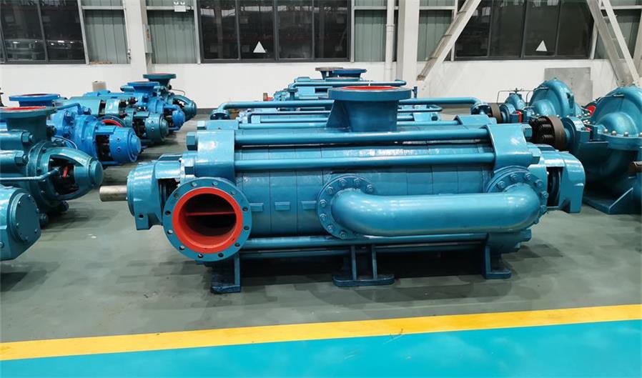
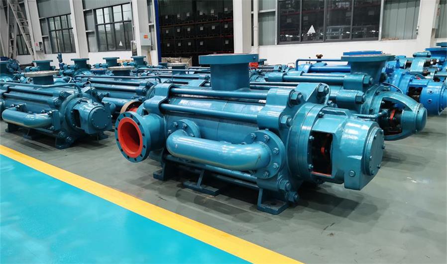
Wear resistant multistage pumps due to many stages, complex structure, disassembly and inspection difficulties, high maintenance costs, the production process requirements are very high, only very few pump factories can produce self balancing wear resistant multistage pumps. Our company has 50 years of experience in multistage pump production. Through daily work and global customer interactions, we understand material performance under various conditions and continuously enhance wear resistance. Our lab uses fluid flow modeling and finite element analysis to develop reliable, efficient, long-lasting, and wear-resistant multistage pumps. These self-balancing pumps offer extended service life, minimal wear and maintenance, and optimal energy efficiency, meeting customer needs and earning their trust.
The hydraulic design optimization of a wear resistant multistage pump has two parts.
The self balancing heavy duty wear resistant multistage pump with reasonable hydraulic design, its operation efficiency is high, the power of the motor is lower, achieve the effect of energy saving and consumption reduction. The wear resistant multistage pump after optimized hydraulic design, operate smoothly, noise and vibrate is lower, spare parts service life is longer, maintenance cycles is longer, finally the cost is less.
The wear of the pump is multiplied with the increase of the pump speed, so the wear-resisting multistage pump under the condition of permitting, as far as possible to choose the low speed operation, which can greatly improve the service life of the impeller, so as to improve the service life of the pump, the speed of the wear-resisting multistage pump is 730-980r/min.
Referring to the advantages of multistage pumps and slurry pumps, the wood mold cutting diagram of blade is designed. Guide vane and annular volute are adopted to ensure hydraulic efficiency. According to the slurry flow characteristics, the design of the square transition pipe, the slurry from the low pressure side to the high pressure side, not only to ensure the flow effect, but also to increase the strength of the pump shell, while greatly reducing the size of the pump, convenient installation and use of the pump.
An Impeller is the core part of the pump, pump capacity, head, efficiency, anti-cavitation performance and characteristic curve are directly related to the hydraulic design of the impeller.
Just as the name implies, the multistage pump has some stages and some impellers. Its shaft design is longer, the pump shaft under radial force will produce a certain amount of deflection. Therefore,the value of impeller wall thickness, the selection of shaft material and structure design are very important. In order to ensure the life under abrasion conditions, the thickness of the impeller wall can not be too thin; On the other hand, in order to reduce the weight of the rotor components, the diameter of the shaft should not be too large, and the thickness of the impeller wall should not be too thick. Our technical department through numerical simulation technology, repeated calculation, comparison, finally determine the most reasonable impeller wall thickness.
Impeller optimization involves a variety of factors such as material, casting process, assembly and so on. If the eccentricity and residual unbalanced mass value of the impeller will make the rotor parts in operation will produce vibration, noise and other phenomena, which directly affects the performance and service life of the pump. After the rotor component is assembled, it must be tested for action balance.
The size of impeller, using the similar calculation method to determine the basic size of impeller; The conventional velocity coefficient method of binary theory was used to optimize the impeller design. By comparing the results of two kinds of calculation, the structure size of pump impeller is finally determined.
When the centrifugal pump impeller is filled with liquid, the motor drives the impeller to rotate rapidly, the blade drives the liquid to rotate, and the liquid flows to the outer edge of the impeller under the action of centrifugal force. At the same time, the outer liquid enters the pump from the suction chamber under atmospheric pressure. The flow of liquid in the impeller is shown in the picture below. The convex surface of the blade is the working face, which does work on the medium, and the space between the two blades is the flow of the medium. The energy of the medium comes from the centrifugal force generated by the rotation of the impeller and the pressure transferred by the blades.
The liquid obtaining pressure continues to enter the next level of impeller inlet along the water flow channel between the two stages, the second stage of the impeller continues to do work on the liquid, and again increase the pressure energy of the liquid, so repeated until the final stage of the impeller, and finally through the pressure discharge chamber out of the pump. Flow constant, head superposition, medium flow principle as shown in the picture below.
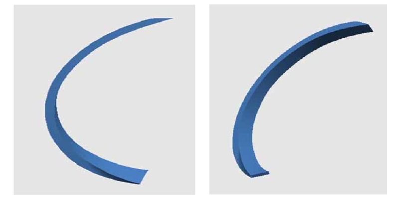
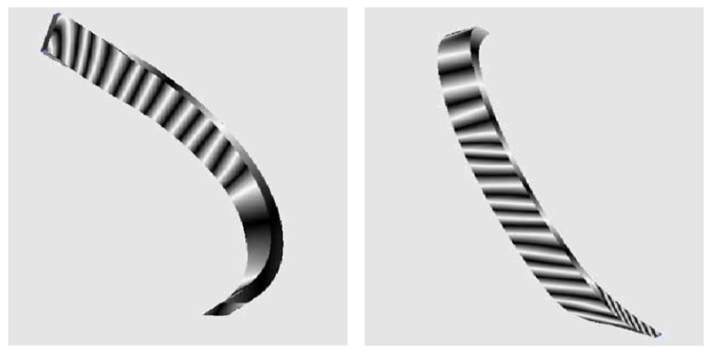
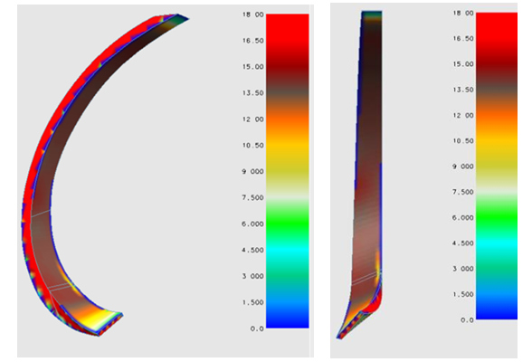
According to the wood mold drawing, 3D drawing of blade shape, blade surface quality check and blade thickness check were carried out.
It can be seen that the blade shape is smooth, regular, smooth distortion, in line with the design requirements. Blade thickness inspection shows that the thinner inlet part can reduce the inlet crowding and improve efficiency, while the thicker middle part can improve the wear resistance of the blade and increase the service life. The thickness transition is uniform without obvious signs of mutation, which meets the time requirements. Hydraulic design should not only take into account the requirements of performance indicators, higher efficiency and lower necessary cavitation allowance, but also make the blade profile in line with the characteristics of medium flow, reduce the wear of the medium to the pump casing.
Application of High Temperature Molten Salt Pumps in the Concentrating Solar Power Plant
Reciprocating Triplex Plunger Pumps For Reverse Osmosis Seawater Desalination: A Comprehensive Guide
What Is A Single Screw Pump? What Is A Progressing Cavity Pump?
The Difference between a Self-Priming Pump and a Centrifugal Pump