Learn - Feb. 08, 2025
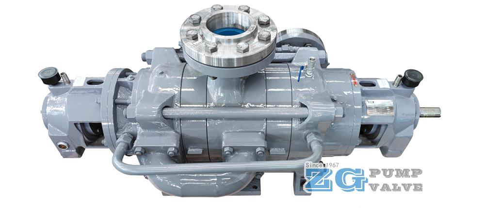
Multistage pumps adopt radial vanes, which have a smaller axial dimension and a larger radial dimension, avoiding the increase in shaft deflection caused by excessive axial length. The flow passage of the radial vane is composed of the forward vane, annular space and backward vane. The forward vane serves as the pressure water chamber, while the backward vane not only has the function of the pressure water chamber but also is responsible for introducing the liquid into the suction chamber of the next stage impeller. The main function of the radial vane is to collect the slurry thrown out by the impeller, convert kinetic energy into pressure energy, and transport it to the next stage impeller at a certain speed. The vane has the dual functions of the suction chamber and the pressure water chamber and is a fixed flow guiding component.
The main parameters and dimensions of radial guide blades are confirmed by the following parts: base circle diameter of radial guide blades (determined by impeller size), guide blade inlet width (axial width), inlet placement Angle, and guide blade throat area.
The performance parameters of heavy-duty wear-resistant multistage pumps are optimized through the optimized design of impellers and radial guide vanes to achieve the best design.
It can be seen from the 3D diagram of guide vane and last stage guide vane that the transition of overflow shape is smooth and uniform, and the shape meets the design requirements. Draw the 3D diagram of guide blade and back blade and check the thickness. It can be seen that the thickness of the blade changes evenly and meets the design requirements.
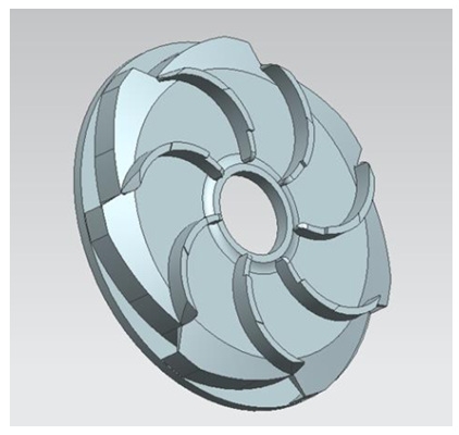
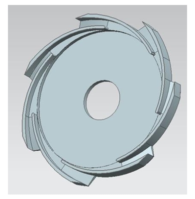
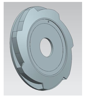
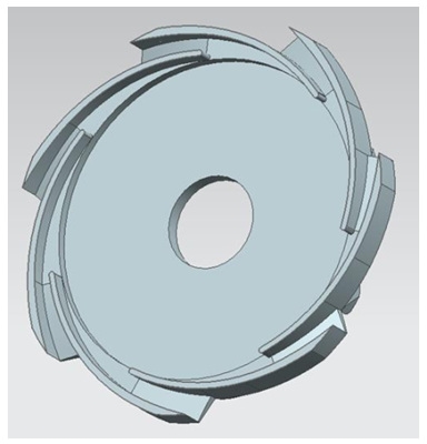
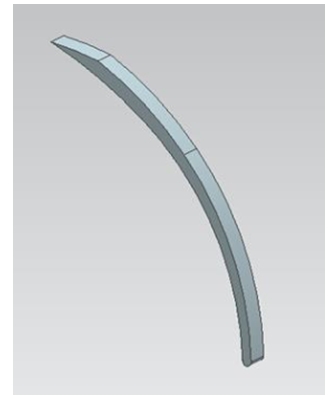
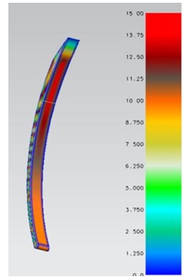
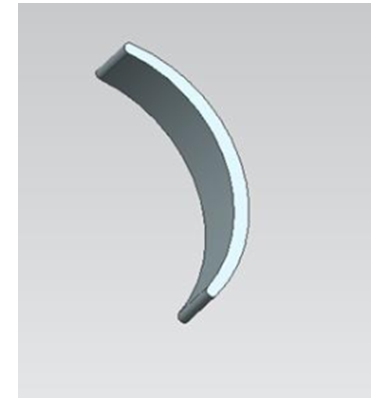
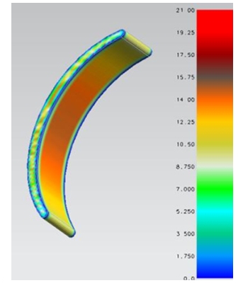
Impellers and guide vanes are important flow parts of a self balancing wear resistant multistage pump, which make sure ability of wear resistance and best hydraulic model.
The dimensions and thick walls of impellers and guide vanes are analyzed through 3D software to ensure the rationality of the design and improve the efficiency of the pump.
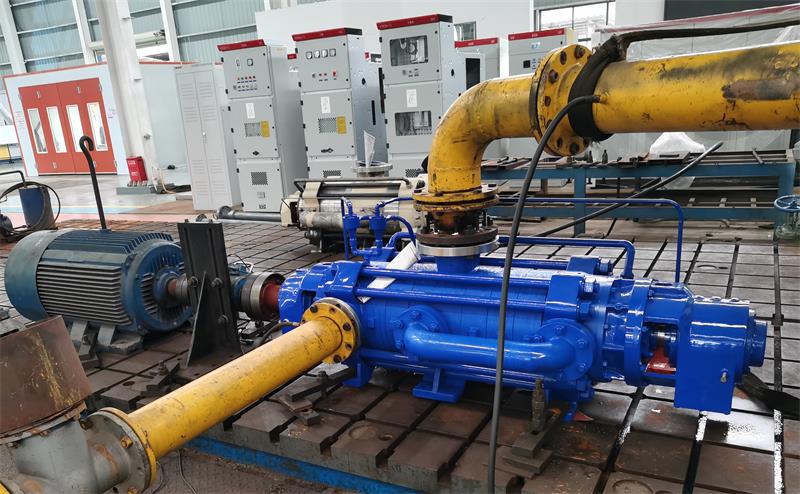
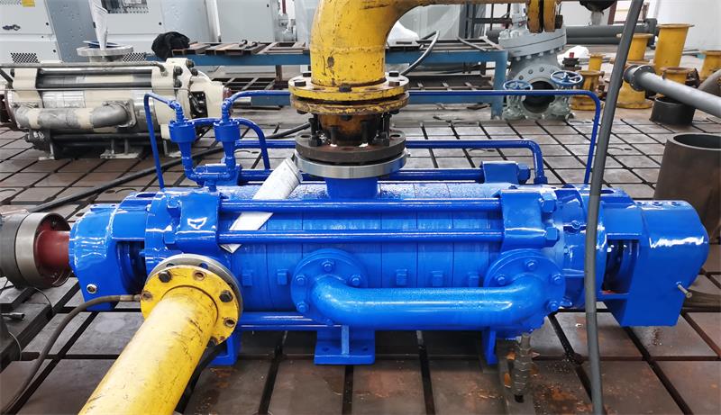
A self balancing wear resisting multistage pump is self balancing horizontal multistage centrifugal structure. The medium inlet can be horizontal or straight up. The medium outlet is arranged vertically upwards. The optimization of the wear resistant multistage pump structure has seven parts: Shaft dimension, rotor component, various pressure sections, mechanical seal, units operation.
A self balancing heavy wear resistant multistage pump adopts bearing structure design at both ends, and adopts back-to-back symmetrical impeller arrangement. This way can balance the axial force generated during operation, so that the axial force of the pump can basically self-balance. The pump is mainly composed of bearing parts, suction section, middle section, water pressure section, impeller, guide vane and other components.
The shaft seal adopts assembled mechanical seal, easy to install, no leakage.
The pump shaft passes through the impellers, and impellers are fixed on the shaft by the keys, shaft sleeves and shaft sleeve nuts. One end of the shaft is equipped with a coupling and connected with the motor.
The shaft is an important part of the transmission unit. Bearings, impellers, throttling bushing and sealing bushing constitute the transmission components, which are fixed on the pump shaft by the flat key and the bushing lock.
The smaller the clearance value between the rotor component and the fixed component, the smaller the pump leakage loss, the higher the efficiency of the pump. The gap value should be reduced as much as possible.
Low pressure suction section is the pump inlet flange to the impeller inlet flow part. The fluid speed of low pressure suction section is small, hydraulic loss is also small, but the shape of the suction section directly affects the slurry flow state in the impeller, has a great impact on the efficiency of the pump. Low pressure suction section has a great impact on the cavitation performance of the pump, so in the design of suction section to ensure that the impeller inlet requirements, in line with the flow direction requirements, reduce hydraulic loss, improve pump efficiency and cavitation performance.
The suction section of the low pressure side is the inlet of the impeller, and the pressure is small. The value of wall thickness mainly considers the casting performance of the material. The value of wall thickness of the suction section of the low pressure side is δ =25mm. By checking the pressure strength of the wall thickness in 3D drawing of the low-pressure suction section, it is confirmed that the pressure capacity meets the design and adapts to the pressure requirements of the working conditions.
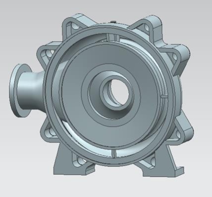
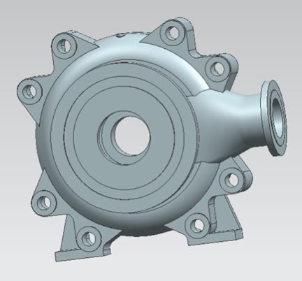
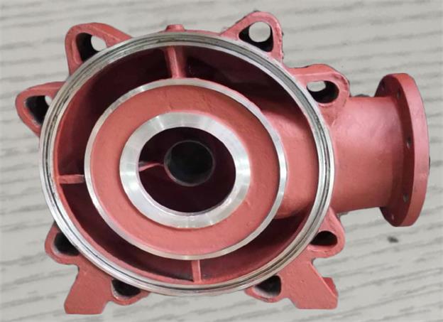
The medium has been pressurized by the multistage impellers to reach the suction section of the high pressure side, and there is already a high pressure. When calculating the wall thickness, the pressure it bears should be fully considered.
The wall thickness is calculated as δ =15mm, and the wall thickness is determined as δ =30mm considering the casting performance of the parts.
By checking the wall thickness strength of the 3D drawing of the high-pressure side suction section, it is confirmed that the pressure capacity meets the design and adapts to the pressure requirements of the working conditions.
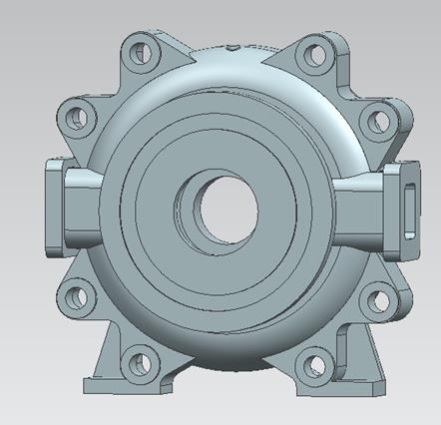
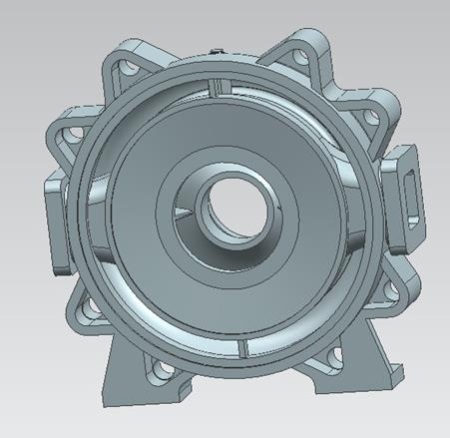
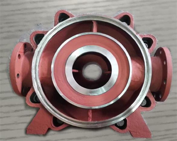
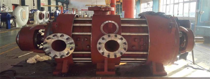
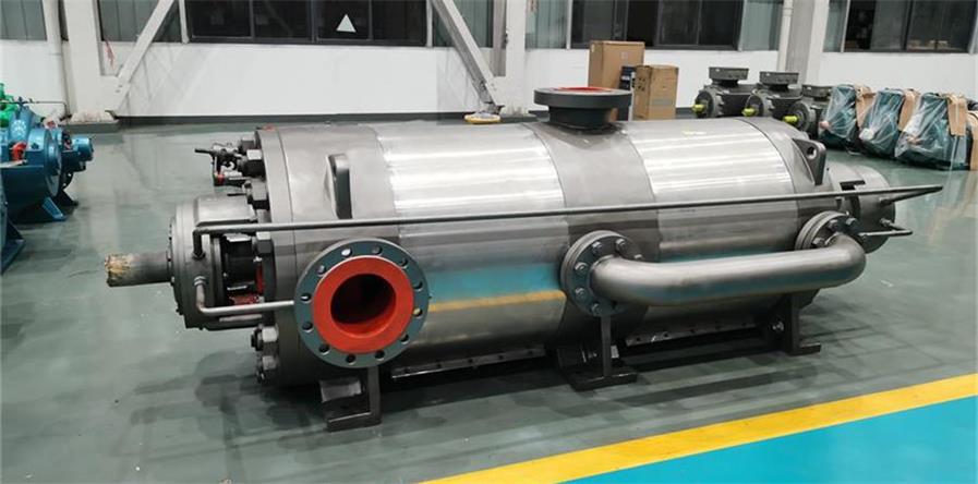
The guide vane is placed in the middle section region, as the shell of the guide vane, to avoid medium leakage. The position of the middle section of the multistage pump can be exchanged, so in the design of the middle section of the wall thickness, according to it can withstand the maximum pressure calculation. The calculation result of the middle wall thickness is: δ =18mm. Considering the casting performance of the parts, the wall thickness is finally determined to be δ =33mm.
By checking the wall thickness strength of the middle section 3D diagram, it is confirmed that the bearing capacity meets the design pressure requirements and adapts to the pressure requirements of the working conditions.
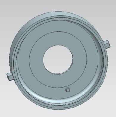
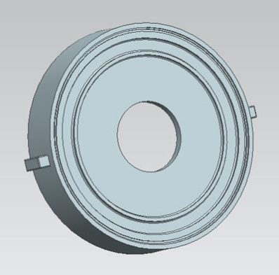
The medium is pressurized by all impellers and finally collected in the outlet section and discharged through the outlet flange. The outlet section bears the highest pressure and the most wear. After the value of wall thickness is calculated by the pressure, a certain safety margin is left. The wall thickness was calculated as δ =20mm, and the wall thickness was determined as δ =33mm considering the casting performance of the parts.
By checking the wall thickness strength of the 3D diagram of the outlet section, it is confirmed that the pressure capacity meets the design and adapts to the pressure requirements of the working conditions. (Figure 3-11, 3-12) Parts pressure is 6. 5Mpa, the maximum stress is far less than the allowable stress of the material.
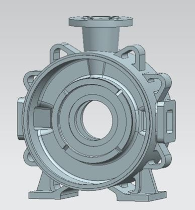
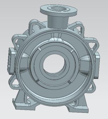
On the whole structure, the self balancing wear resistant multistage pump is optimized and improved on the basis of the D type multistage pump. The impellers are arranged back-to-back symmetrically to balance the axial force generated by the impellers. The internal structure is divided into low pressure lateral cavity and high pressure lateral cavity. In order to prevent the medium in the high pressure lateral cavity from leaking to the low pressure lateral cavity, the throttling sleeve device is designed in the middle of the low pressure side and the high pressure side.
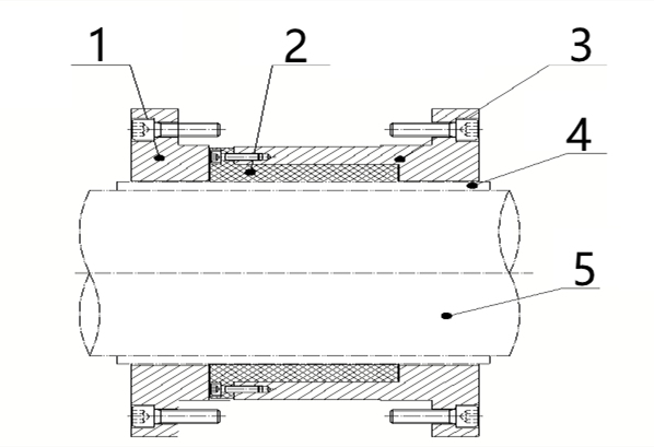
| 1.Throttle gland | 2.lining of throttle sleeve | 3.Seat of throttle | 4.Shaft sleeve of throttle | 5.Shaft |
The throttling sleeve device is composed of throttling gland, throttling bushing, throttling body, throttling sleeve and other parts.
Heavy multistage centrifugal pump transport medium contains solid particles. Throttling gland, throttling body and throttling sleeve are made of wear-resistant material, and throttling bushing is made of PTFE.
The medium transported by wear resistant multistage pump contains certain solid particles. Sometimes the pressure of the shaft seal is as high as 2MPa. The purpose of no leakage and long life can be achieved by using mechanical seal. If the conveying medium contains small particulates, and the concentration is low, this situation could use a single mechanical seal without flushing water; If the conveying medium contains a large concentration of particles, this situation must use double mechanical seal with flushing water.
Based on the analyzing structural features, select shaft diameter, calculate pressure-bearing and thickness of the important parts, adopt double mechanical seal, all of these could improve the reliability of the pump operation.